Flink RPC
架构设计
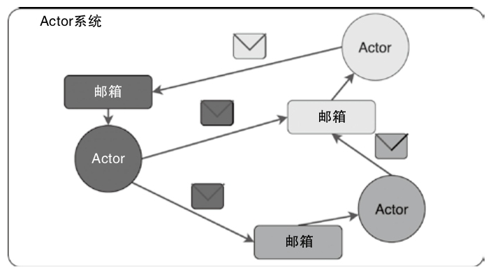
Akka
- 使用Scala语言编写的库,用于在JVM上简化编写具有可容错、高可伸缩性的Java或Scala的Actor模型
- 状态:Actor对象的变量信息,由Actor自己管理,避免了并发环境下的锁和内存原子性等问题
- 行为:指定Actor中的计算逻辑,通过接收到消息改变Actor的状态。
- 邮箱:每个Actor都有自己的邮箱,通过邮箱能简化锁及线程管理。邮箱是Actor之间的通信桥梁,邮箱内部通过FIFO消息队列存储Actor发送方的消息,Actor接收方从邮箱队列中获取消息
构建 Akka 的例子
|
|
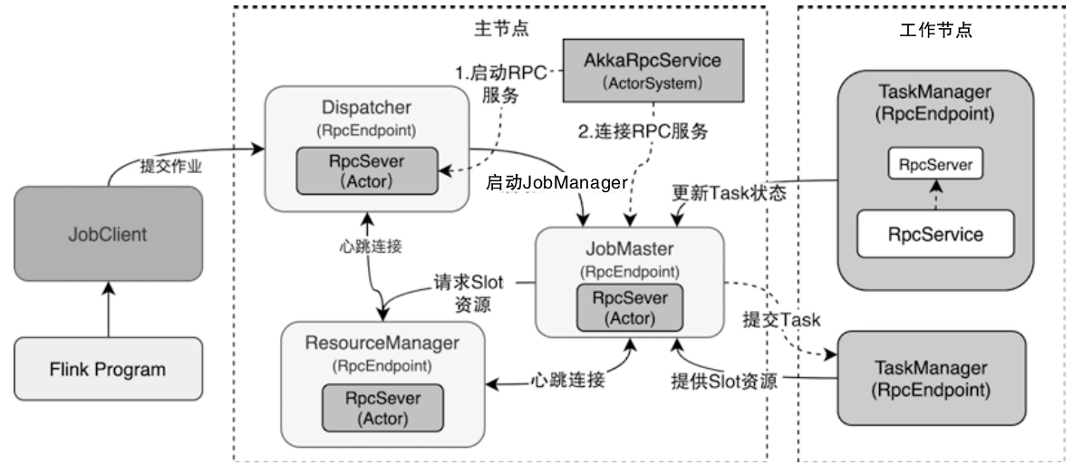
Flink RPC节点调用关系图
- 集群的RPC服务组件是RpcEndpoint
- 每个RpcEndpoint包含一个内置的RpcServer负责执行本地和远程的代码请求,RpcServer对应Akka中的Actor实例
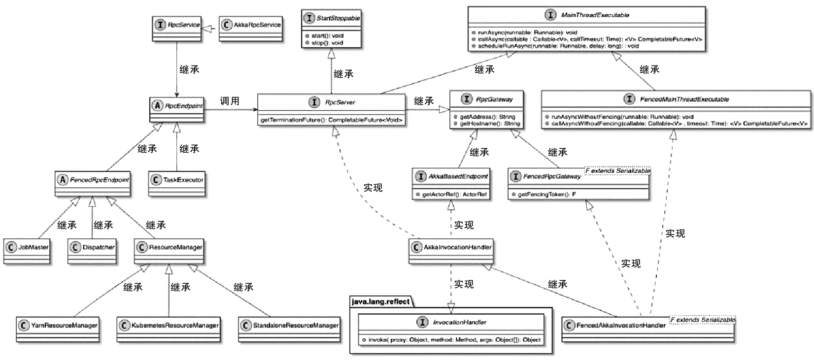
Flink RPC 相关类图
- RpcEndpoint中提供了集群RPC组件的基本实现
- 所有需要实现RPC服务的组件都会继承RpcEndpoint抽象类
- RpcEndpoint借助RpcService启动内部RpcServer,之后通过RpcServer完成本地和远程线程执行
- FencedRpcEndpoint 增加了 toke,只有访问的 token 一致才会调用
- 实现类有Dispatcher、JobMaster以及ResourceManager等
- RpcService提供了创建和启动RpcServer的方法
- RpcServer接口通过AkkaInvocationHandler动态代理类实现
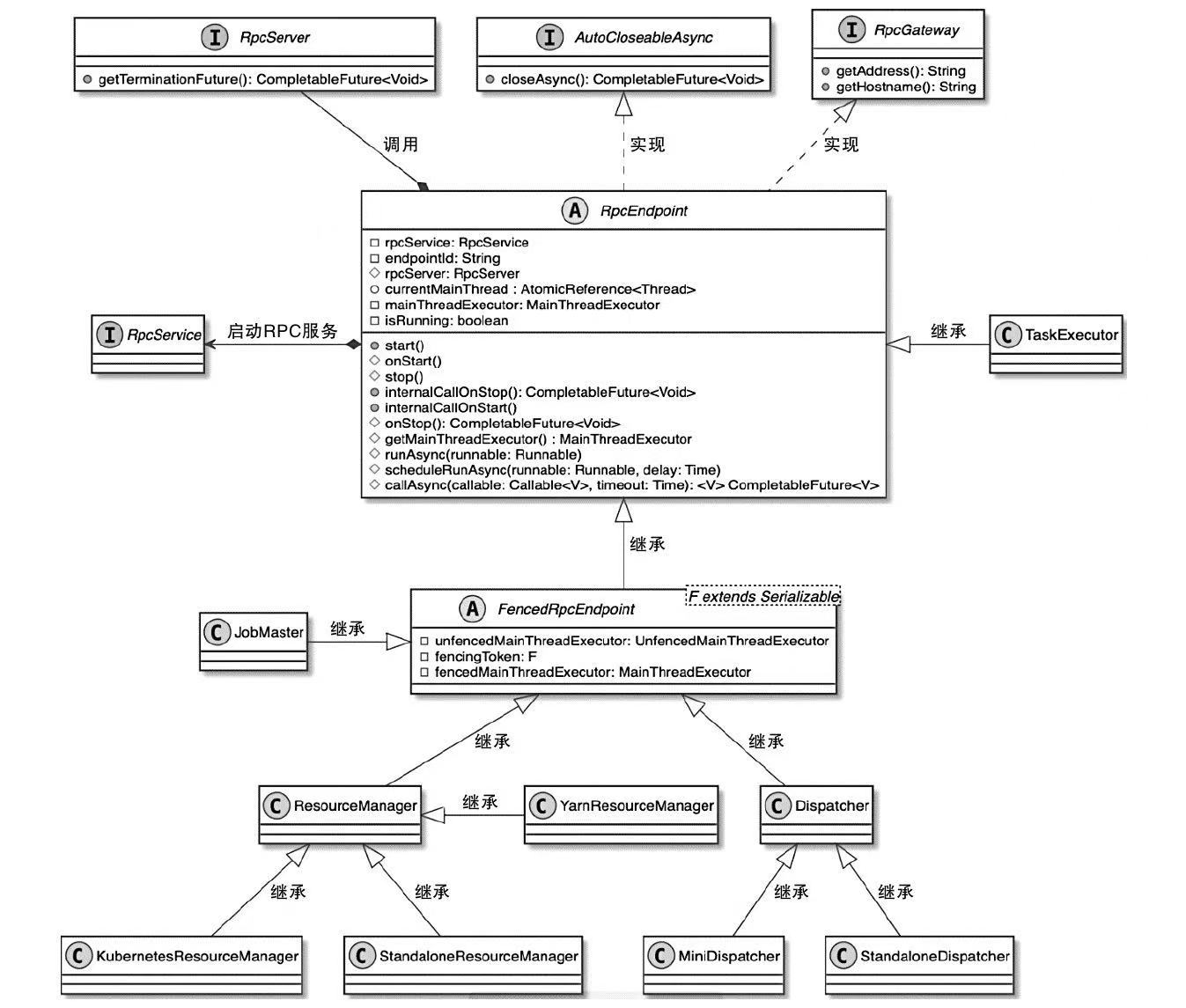
RpcEndpoint 相关类图
- RpcEndpoint实现了RpcGateway和AutoCloseableAsync两个接口
- RpcGateway提供了动态获取RpcEndpoint中Akka地址和HostName的方法
AkkaRpcService 相关类图
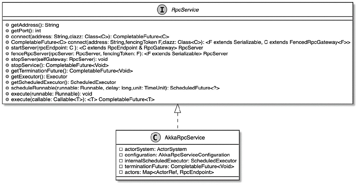
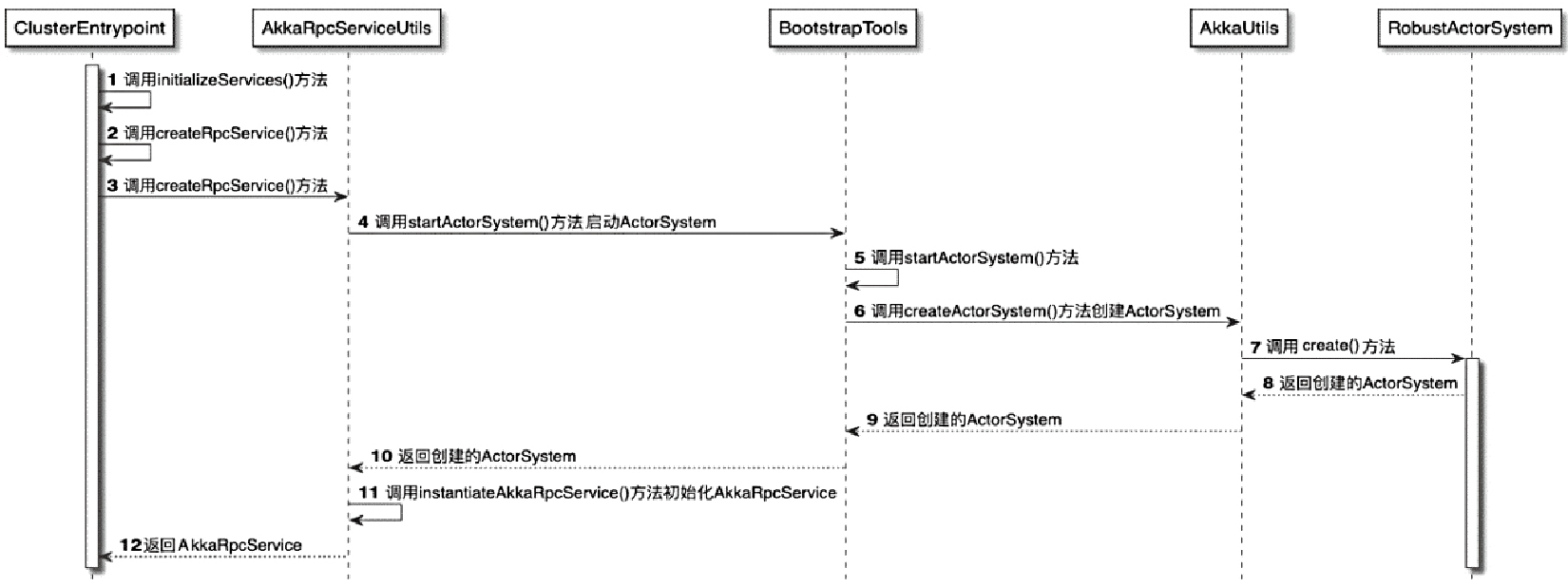
ClusterEntrypoint中创建AkkaRpcService过程
Akka 的例子,服务端
|
|
客户端的例子
|
|
RpcServer启动流程图
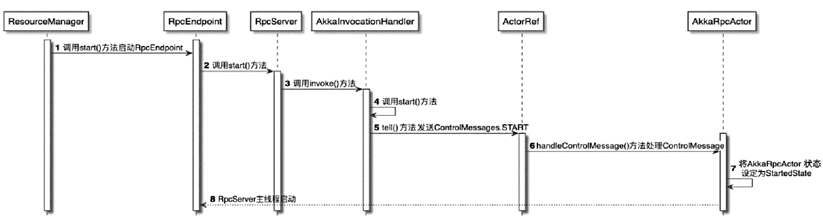
RpcServer动态代理实现
- 最终都会通过AkkaInvocationHandler.invoke()方法进行代理实现
- 根据在本地执行还是远程执行将代理方法进行区分
AkkaRpcActor
- RemoteRpcInvocation消息,最终会通过Akka系统传递到被调用方
- 如TaskExecutor向ResourceManager发送SlotReport请求
- 将 ResourceManagerGateway的方法名称和参数打包成RemoteRpcInvocation对象
- 然后经过网络发送到ResourceManager中的AkkaRpcActor
集群组件之间的RPC通信
- 当TaskExecutor启动后,会立即向ResourceManager中注册当前TaskManager的信息
- JobMaster组件启动后也立即会向ResourceManager注册JobMaster的信息
- 这些注册操作实际上就是在构建集群中各个组件之间的RPC连接
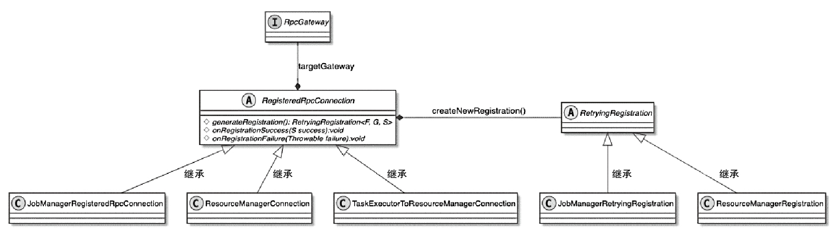
RegisterdRpcConnection 相关类图
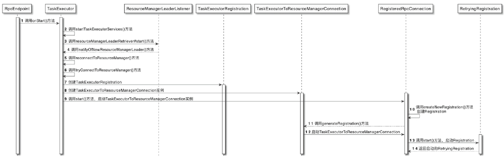
TaskManager向ResourceManager注册RPC 服务的流程
- TaskExecutor调用startTaskExecutorServices()方法启动TaskExecutor的内部组件服务
- ResourceManagerLeaderListener接收到来自ResourceManager 信息后,通知TaskExecutor和新的ResourceManagerLeader建立RPC连接
- 创建与ResourceManager组件之间的RPC网络连接
- 在connectToResourceManager()方法中会创建TaskExecutorRegistration对象,用于存储TaskManager的注册信息
- 建TaskExecutorToResourceManagerConnection实例,正式与ResourceManager建立RPC网络连接
- 最终完成在ResourceManager中注册TaskManager的操作。创建的TaskExecutorRegistration同时会传递给ResourceManager
NetworkStack
StreamTask 数据流
TaskManager和TaskManager节点之间 也有通讯
- Task之间的数据交换
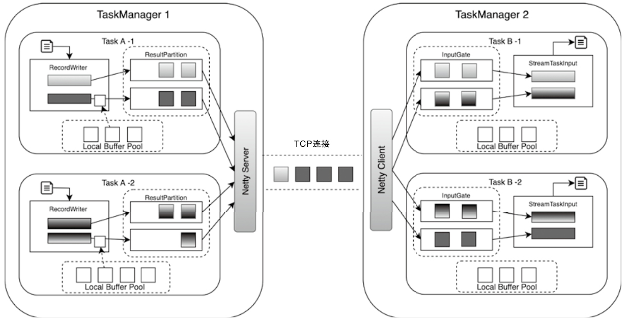
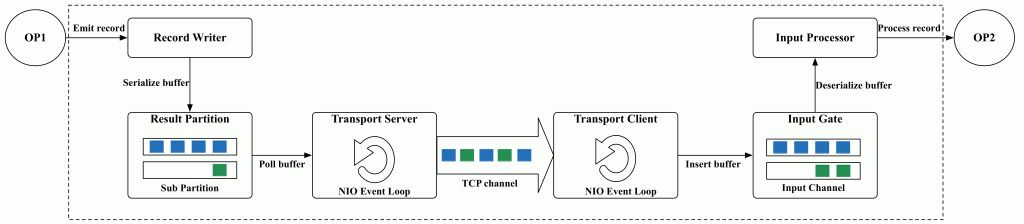
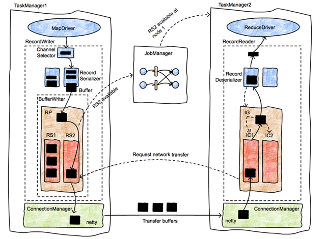
Flink NetworkStack整体架构
- 整个数据传输过程主要基于Flink的NetworkStack框架进行
- 经过Operator处理后的数据,最终会通过RecordWriter组件写入网络栈
- 先将数据转为 二进制 buffer 数据,并缓存在 ResultSubPartition队列中
- 上游的Task中会创建LocalBufferPool为数据元素申请对应Buffer的存储空间
- 上游的Task会创建NettyServer作为网络连接服务端,并与下游Task内部的NettyClient之间建立网络连接
- 下游的Task实例,会通过InputGate组件接收上游Task发送的数据
- 上游Task的ResultPartition会根据ChannelSelector选择需要将数据下发到哪一个InputChannel中,类似娱 Shuffle 操作
- 下游收到后会缓存到本地的 buffer 队列中
- 之后被 StreamTaskInput 不断从队列中拉取出来并处理
OneInputStreamTask结构图
- 根据数据源不同,StreamTask分为两种类型
- 直接从外部源数据读取数据的SourceStreamTask和SourceReaderStreamTask
- 支持从网络或本地获取数据的OneInputStreamTask和TwoInputStreamTask
- DataOutput:负责将StreamTaskInput接收的数据发送到当前Task实例的OperatorChain的HeadOperator中进行处理
- 主要有StreamTaskNetworkOutput和StreamTaskSourceOutput两种实现
- 在 OperatorChain中:上一个算子处理的 数据会通过Output组件发送到下一个算子中继续处理
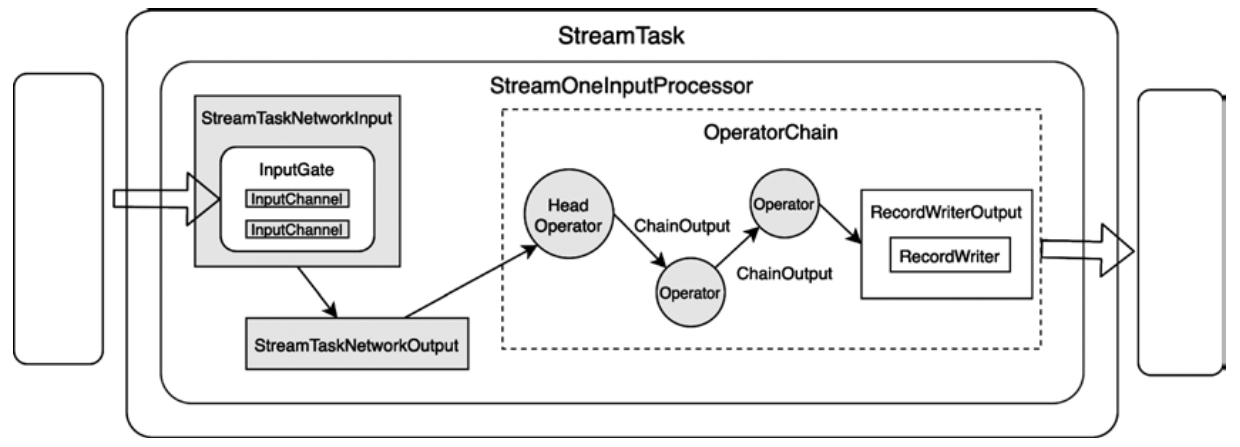
Output 组件的实现主要有
- ChainingOutput
- BroadcastingOutputCollector
- DirectedOutput
- RecordWriterOutput 等
StreamTaskNetworkInput.
- 不断的从上游获取数据,写入 buffer
- 判断 数据类型
- StreamRecord
- WaterMark 类型
- LatencyMarker 类型
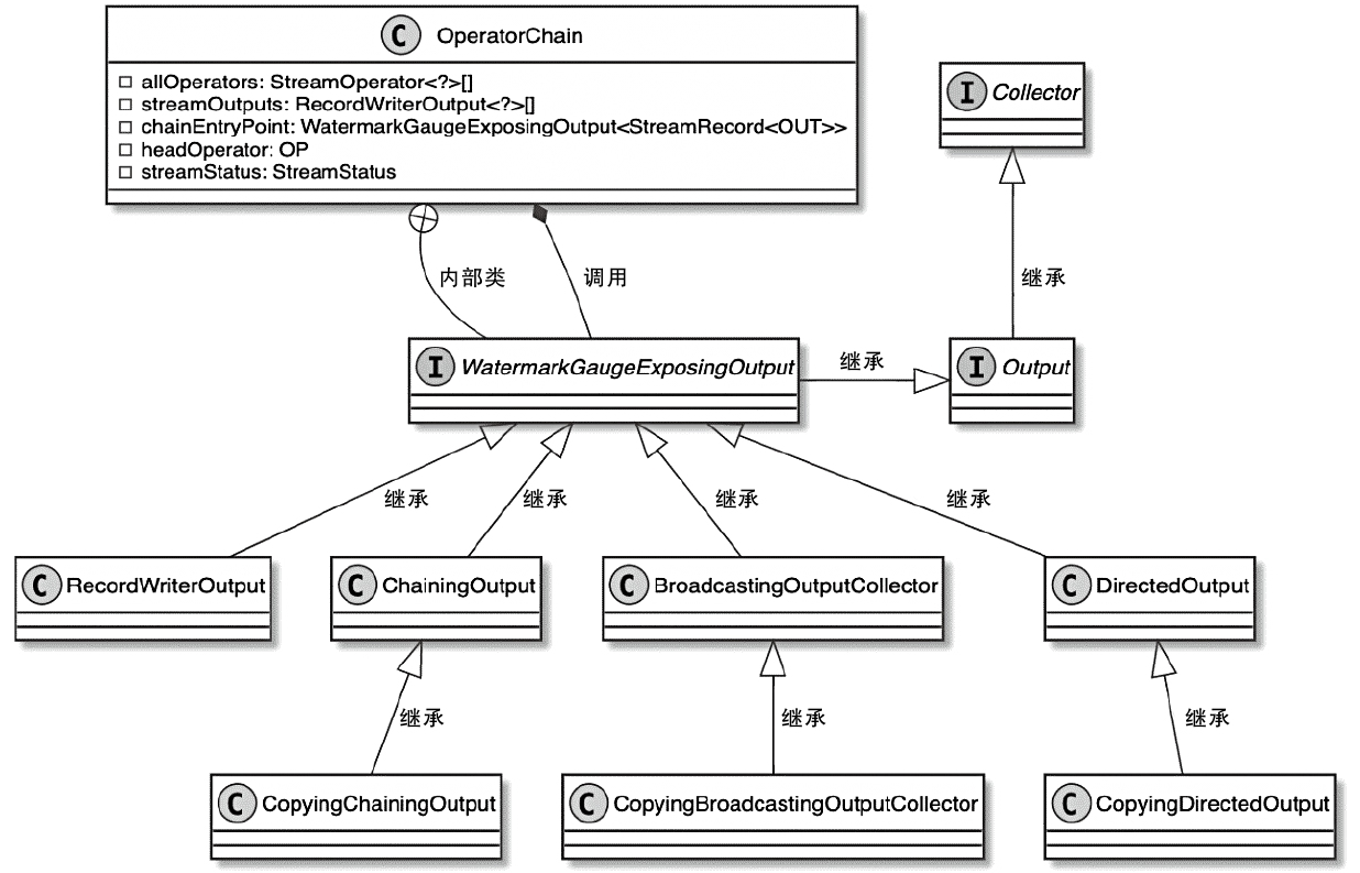
OperatorChain 相关类图
RecordWriter
RecordWriter
- StreamTask节点中的中间结果数据元素最终通过RecordWriterOutput实现了网络输出
- RecordWriterOutput底层依赖RecordWriter组件完成数据输出操作
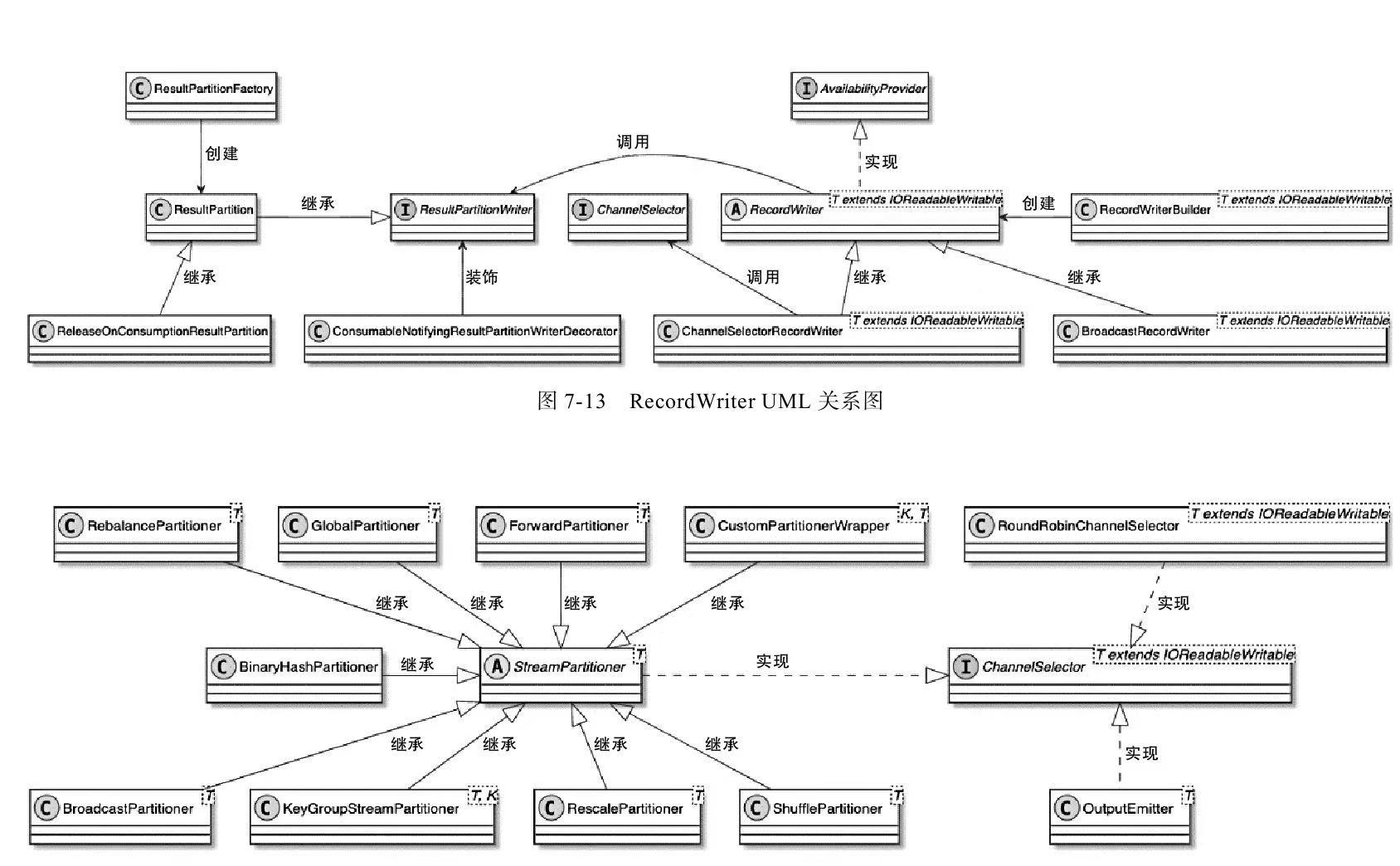
RecordWriter主要有两种实现类
- ChannelSelectorRecordWriter,内部基于StreamPartitoner获取不同的数据下发策略,实现数据重分区
- BroadcastRecordWriter,广播下发
ChannelSelectorRecordWriter 相关类图
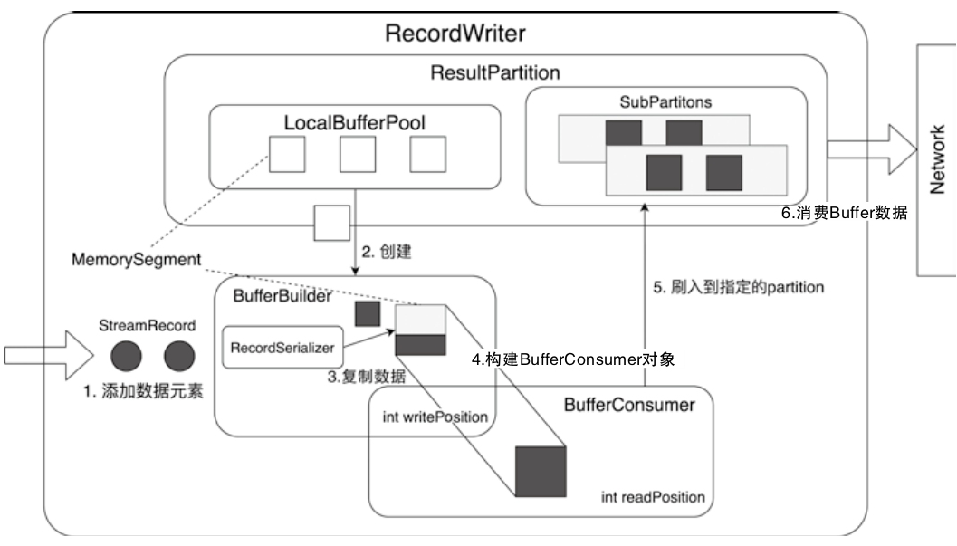
RecordWriter 设计与实现
- BufferBuilder中会不断接入ByteBuffer数据,直到将BufferBuilder中的Buffer空间占满
- 填满后,会向下游输出
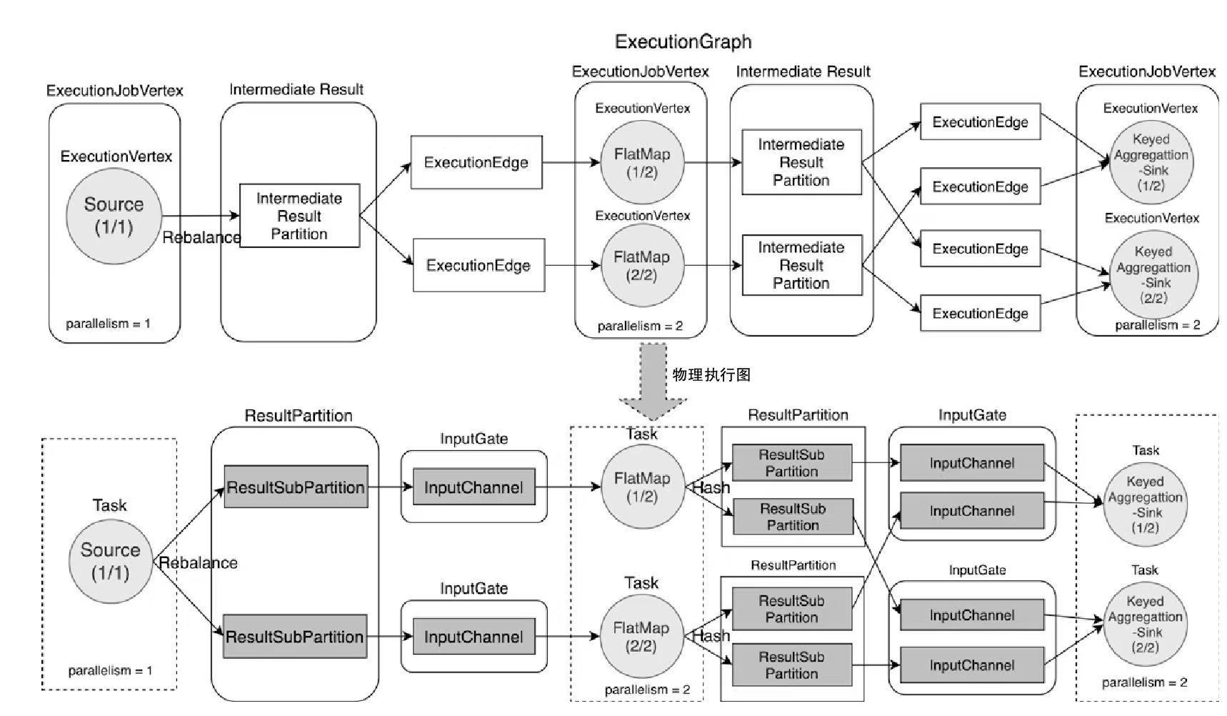
ExecutionGraph与物理执行图
Shuffle 相关
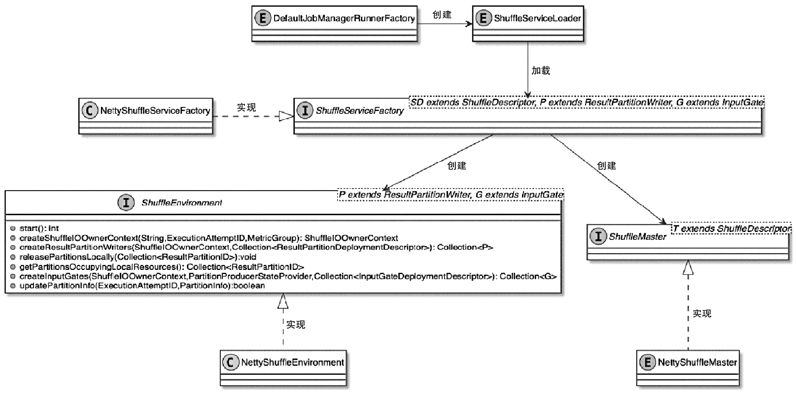
ShuffleService 相关类图
- 为支持可插播的 shuffle管理,通过 SPI方式加载到 classloader 中
- JobManagerRunner 实例的过程中会创建 ShuffeServiceLoader,TaskManager也是类似的
- ShuffleServiceFactory 创建 shuffle
- ShuffleEnvironment组件提供了创建Task实例中ResultPartition和InputGate组件的方法
- ShuffleMaster组件实现了对ResultPartition和InputGate的注册功能
shuffle 的创建
- JobMaster中创建 ShuffleMaster
- 在TaskManager中创建 ShuffleEnvironment
ShuffleMaster (JobManager-side):
- Responsible for global shuffle resource management, including requesting/releasing resources (e.g., network connections, storage allocations).
- Generates ShuffleDescriptor objects that encode metadata about data locations (e.g., remote worker addresses, file paths).
- Coordinates with the scheduler to ensure resource availability during task deployment
ShuffleEnvironment (TaskManager-side)
- Manages local shuffle resources such as network buffers, memory pools, and I/O handlers.
- Creates ResultPartitionWriter (producer) and InputGate (consumer) instances for data transmission.
- Handles buffer recycling and network connection lifecycle.
上下游算子交互过程
TaskManager 中,createNettyShuffleEnvironment() 过程如下:
- 获取相关配置,如:TransportType、InetAddress、serverPort以及numberOfSlots等信息
- 创建ResultPartitionManager实例,专门用于消费ResultSubpartition中的Buffer数据
- 创建FileChannelManager实例,会将数据写入文件系统,再对文件进行处理,这里的实现和MapReduce算法类似
- 创建ConnectionManager实例,主要用于InputChannel组件
- 创建NetworkBufferPool组件
- 向系统中注册ShuffleMetrics
- 创建ResultPartitionFactory工厂类,用于创建ResultPartition
- 创建SingleInputGateFactory工厂类,用于创建SingleInputGate
多个算子写入、读取的网络过程
ResultPartition
ResultPartition
- 实际上是ExecutionGraph 中 IntermediateResultPartition 对应的底层物理实现
- 通过 ResultPartition 实现管理和缓存Task产生的中间结果数据
- 每个Task中都有一个 ResultPartition,会根据并行度创建多个 ResultSubPartition
ResultPartition 相关类图
- 单个 ResultPartition 会包含多个 ResultSubPartiton 实例
- ResultSubPartiton 的数量取决于 ExecutonGraph 中 IntermediateResult 的分区数
- ResultSubPartiton 的数量和下游 InputGate 中 InputChannel 的数量保持一致
- PipelinedSubParitition主要用于无界流式数据处理场景
- BoundedBlockingParitition主要用于有界离线数据处理场景
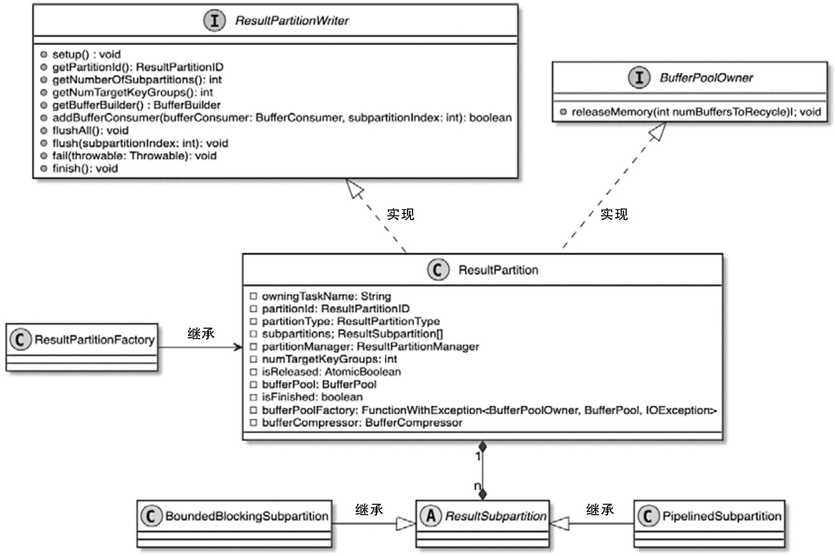
ResultPartition 的子类
PipelinedResultPartition
- Purpose: Designed for streaming/pipelined execution.
- Enables in-flight data transfer between producers and consumers.
- Supports low-latency processing by emitting data immediately.
- Uses network buffers for backpressure management.
BoundedBlockingResultPartition
- Purpose: Optimized for batch/blocking execution.
- Writes data to persistent storage (disk or remote storage) before consumers read.
- Supports blocking data exchanges (full materialization of results).
- Enables efficient bulk reads for downstream tasks.
HsResultPartition (Hybrid Shuffle)
- Purpose: Part of Flink’s Hybrid Shuffle mechanism (batch + streaming).
- Combines in-memory buffering and disk spillover for large datasets.
- Dynamically switches between pipelined and blocking modes.
- Optimized for elastic resource scaling (e.g., Kubernetes environments).
SortMergeResultPartition
- Purpose: Specialized for sorted data exchanges.
- Writes data in sorted runs (pre-sorted chunks).
- Merges sorted runs during consumption (via SortMergeInputGate).
- Minimizes memory usage for large-scale sorting.
BufferWritingResultPartition
- Purpose: Base class for direct buffer management.
- Handles low-level buffer allocation and recycling.
- Provides common logic for both pipelined and blocking writes.
- Extended by PipelinedResultPartition and BoundedBlockingResultPartition.
Key Architectural Roles
- Streaming vs. Batch
- Pipelined* for streaming (low latency).
- BoundedBlocking*/SortMerge* for batch (high throughput).
- Hybrid Shuffle:
- HsResultPartition bridges streaming and batch for adaptive execution.
- Performance Tradeoffs:
- Pipelined: Lower latency but higher memory pressure.
- Blocking/SortMerge: Higher throughput but requires materialization.
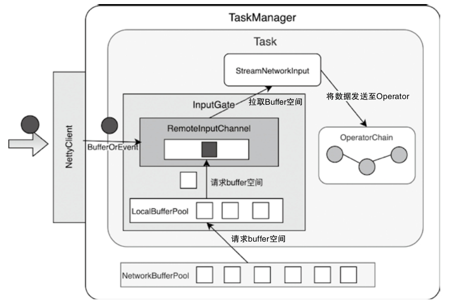
InputGate的设计与实现
- 下游 Task 节点中的 InputGate 和上游 ResultPartition 对应
- InputGate 同样包含了一个 LocalBufferPool 组件
- 通过将 InputGate 封装成 CheckpointedInputGate,可以实现对 Checkpoint 数据的处理
- 借助 StreamTaskNetworkInput 中的 DataOut 组件将数据推送到 OperatorChain 中进行处理
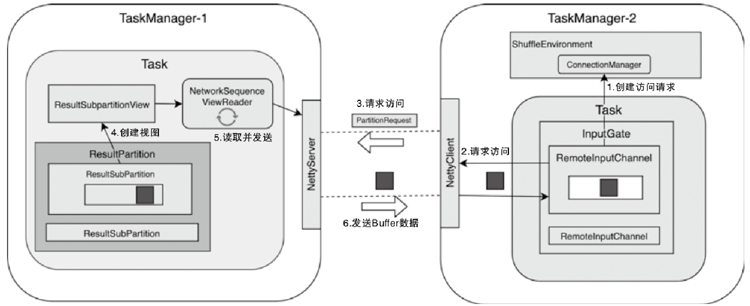
InputChannel向ResultPartition发送数据访问请求
- InputChannel 调用 ConnectionManager 创建用于访问上游 Task 实例中 ResultPartition 的 PartitionRequestClient 对象
- 调用PartitionRequestClient向网络中发送PartitionRequest消息,包括:PartitionId、SubpartitionIndex、InputChannelId 和 InitialCredit 等信息
- 创建 NetworkSequenceViewReader 组件,用于读取 ResultSubPartition 中的数据
- 下游的 RemoteInputChannel 从 Channel 中获取 BufferOrEvent 数据
- Task 通过 InputGate 中的 InputChannel 组件获取上游发送的 Buffer 数据,然后经过 DataOut 组件将其发送到 OperatorChain 中进行处理
InputChannel 实现
- LocalInputChannel
- RemoteInputChannel
Core Reasons for Multiple RemoteInputChannels
1. Parallel Data Consumption
- A single InputGate typically represents a logical input (e.g., one partition of data).
- However, data might come from multiple upstream ResultSubpartitions (e.g., from different TaskManagers or different subpartitions of the same ResultPartition).
- Each RemoteInputChannel corresponds to a connection to a specific ResultSubpartition (e.g., from TaskManager-1’s ResultSubPartition to TaskManager-2’s InputGate).
2. Shuffling or Partitioned Data -During operations like keyBy, shuffle, or rebalance, data is split into partitions sent to downstream tasks.
- Each RemoteInputChannel handles data from one upstream partition.
- Example: If TaskManager-1’s ResultPartition has 3 subpartitions, TaskManager-2’s InputGate will create 3 RemoteInputChannels to read them in parallel.
3. Pipelined vs. Blocking Exchanges
- For pipelined execution (streaming), data flows immediately through channels.
- For blocking exchanges (batch), channels are created once all upstream data is produced.
- Multiple channels allow overlapping consumption (fetching data while processing).
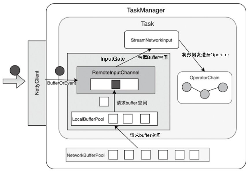
InputChannel中Buffer数据接入的过程
ConnectManager
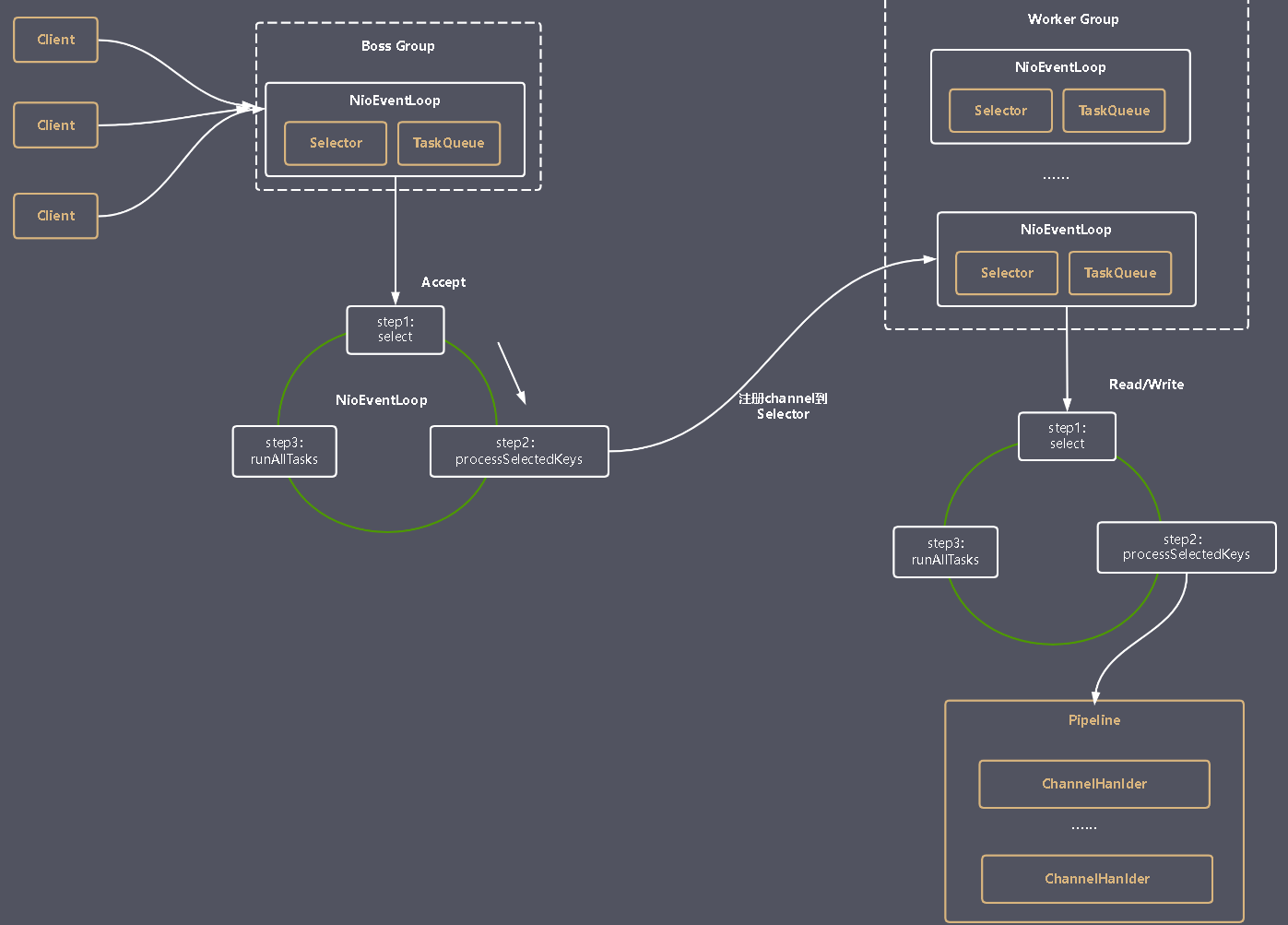
Netty Reactor架构图
- Boss Group用于处理网络连接
- Worker Group用于处理实际的读写IO
- Worker Group和Boss Group都会执行一个runAllTasks()方法,用于处理任务队列中的任务。
- 任务队列包括用户调用eventloop.execute()或schedule()方法执行的任务以及其他线程提交给该EventLoop的任务
- Channel代表一个实体(如硬件设备、文件、网络套接字、能够执行一个或者多个I/O操作的程序组件)的开放链接,如读操作和写操作
- ChannelHandler用于处理业务逻辑
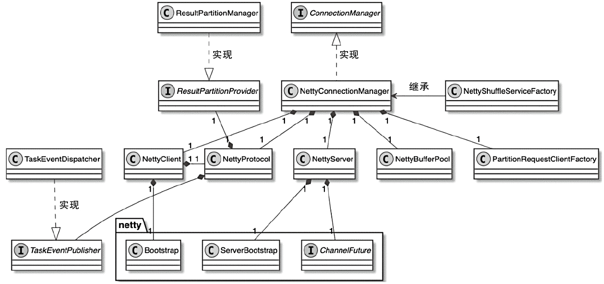
ConnectorManager 相关类图
- 属于TaskManager中网络环境对象(ShuffleEnvironment)的核心部件
- 默认实现是NettyConnectionManager,实际上就是基于Netty框架实现的网络连接管理器
- TaskManager中的NettyConnectionManager会同时管理一个Netty客户端(NettyClient)实例和一个Netty服务端(NettyServer)实例
- NettyConnectionManager中包含NettyServer、NettyClient、NettyProtocol、NettyBufferPool和PartitionRequestClient等成员变量
NettyConnectionManager 构造函数
|
|
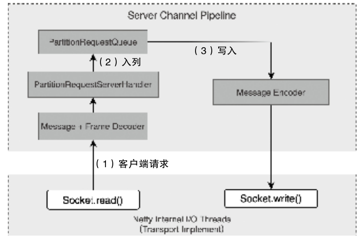
ServerChannelHandler的创建和获取
- 有NettyMessageEncoder、NettyMessageDecoder、PartitionRequestServerHandler和PartitionRequestQueue- 客户端的请求被 read 后,解码放入队列
- 通过 MessageEncoder 对 Buffer 数据进行编码,执行 Socket#write()
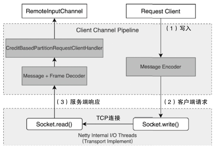
ClientChannelHandlers的创建和获取
- 主要包括 NettyMessageEncoder、NettyMessageDecoder以及CreditBasedPartitionRequestClientHandler
- 发送到 RemoteInputChannel 的 Buffer 队列中,供下游的算子消费
流入 和 流出接口
- ChannelInboundHandler
- ChannelOutboundHandler
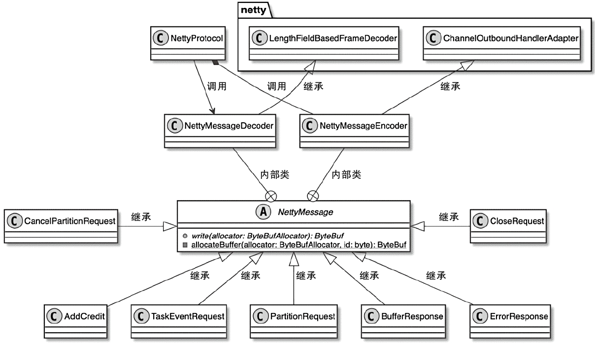
NettyMessage 相关类图
- NettyClient-NettyServer方向(从RemoteInputChannel到ResultPartiton)
- PartitionRequest、CancelPartitionRequest、AddCredit、TaskEventRequest、CloseRequest
- NettyServer-NettyClient方向(从ResultSubPartiton到RemoteInputChannel)
- BufferResponse、ErrorResponse
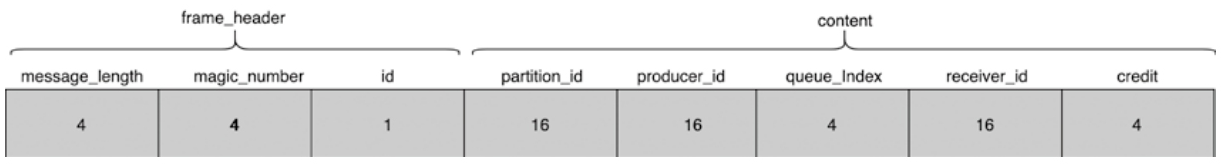
PartitionRequest内存空间申请
- PartitionRequest中的信息会按照顺序依次写入ByteBuf中,最后再将ByteBuf result通过Netty发送到TCP网络中
Buffer 中的数据类型,源码中用DataType表示
|
|
RemoteInputChannel
- 本地维系 expectedSequenceNumber,只有两边的序列号相同才能证明 Buffer 数据的顺序是正常的且可以进行处理
- 判断Backlog是否大于0,如果是则说明上游ResultSubPartition还有更多Buffer数据需要消费,此时调用onSenderBacklog(backlog)方法处理Backlog信息
InputGate 作用
- Aggregating Input Channels
- An InputGate acts as a logical gateway that aggregates multiple InputChannels (physical connections to upstream ResultSubpartitions).
- Each InputChannel corresponds to a specific upstream partition (e.g., a subpartition of a ResultPartition)
- Coordinating Data Consumption
- The InputGate coordinates the data request and delivery process:
- Requesting partitions: It triggers requestPartitions() to initiate data consumption from upstream subpartitions via InputChannels (e.g., - LocalInputChannel or RemoteInputChannel).
- Buffering and sequencing: It manages buffers (via BufferPool) to handle backpressure and ensures ordered data delivery to the task thread. - Handling events: It processes metadata like EndOfPartitionEvent or CheckpointBarrier to track data completeness and align checkpoints
- Resource Management - Memory allocation: The InputGate manages buffer pools (bufferPool) to allocate memory segments for incoming data, balancing throughput and backpressure.
- Slot sharing: In scenarios with slot sharing (e.g., tasks from different operators in the same slot), the InputGate ensures isolation of data streams while sharing resources
4. Fault Tolerance
- Checkpoint alignment: By tracking CheckpointBarrier propagation across InputChannels, the InputGate ensures consistent state snapshots.
- Error handling: If an InputChannel fails (e.g., network issues), the InputGate notifies the JobManager to trigger recovery (e.g., restarting affected tasks)
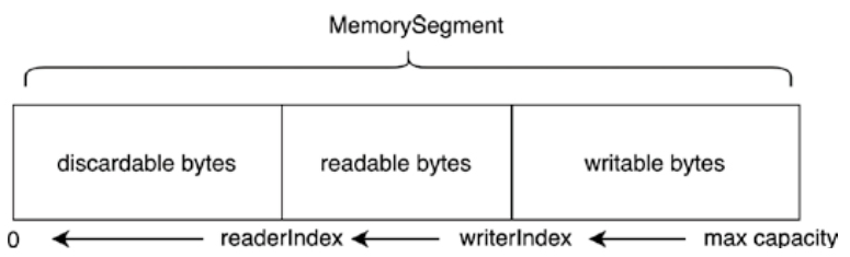
NetWorkBuffer
NetworkBuffer内部分段
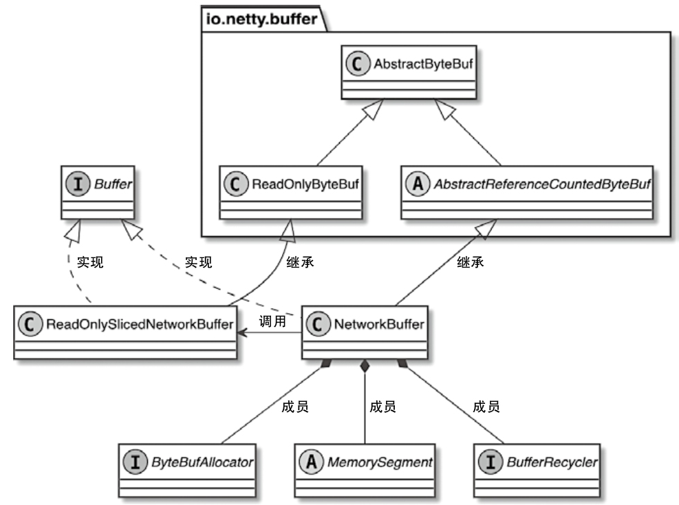
- Buffer接口分别被NetworkBuffer和ReadOnlySlicedNetworkBuffer类继承和实现
NetworkBuffer 相关类图
- MemorySegment是NetworkBuffer底层使用的内存块
- BufferRecycler主要负责对当前Buffer进行内存空间的回收
- ByteBufAllocator是Netty中用于分配内存的组件
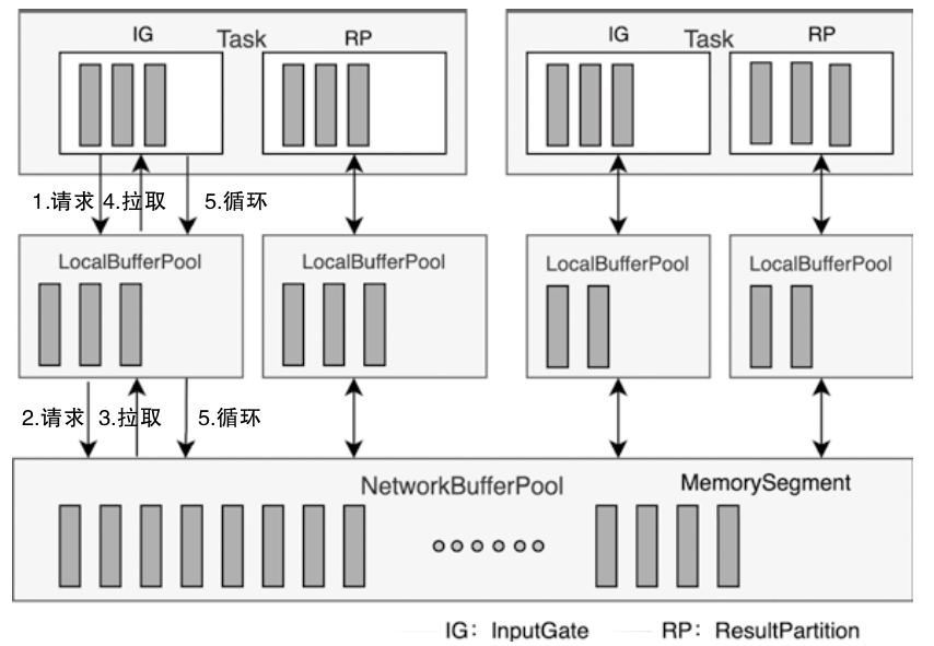
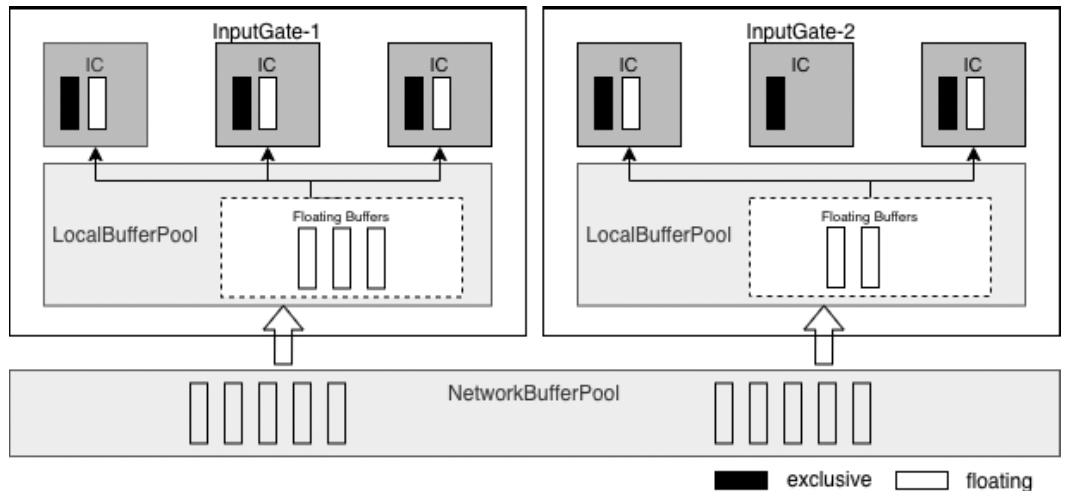
NetworkBufferPool与LocalBufferPool关系图
- 当创建Task线程时,默认通过ShuffleEnvironment创建InputGate和ResultPartition
- 分别为Task中的InputGate(IG)和ResultPartition(RP)组件创建一个LocalBufferPool(本地缓冲池)
- 其中InputGate对应的缓冲池初始内存块数量与InputGate中的InputChannel数量一致
- ResultPartition对应的缓冲池初始内存块数量与ResultPartition中的ResultSubpartition数量一致
NetworkBufferPool与LocalBufferPool 关系
1、Hierarchy and Ownership
NetworkBufferPool:
- A global, TaskManager-level memory pool shared by all tasks running on the same TaskManager.
- Allocates fixed-size MemorySegments (default: 32 KB each) from off-heap or heap memory during TaskManager initialization.
- Manages a static number of buffers (default: 2048 segments, totaling 64 MB).
LocalBufferPool:
- A task-specific buffer pool created for each InputGate (input) or ResultPartition (output) within a task.
- Acts as a logical subset of the NetworkBufferPool, dynamically borrowing buffers as needed
2、Buffer Allocation Mechanism
Initialization:
- When a task starts, Flink creates LocalBufferPools for its inputs/outputs, setting initial buffer limits based on parallelism (e.g., one buffer per channel).
- LocalBufferPools initially hold no buffers; they request them from the NetworkBufferPool on demand.
Dynamic Borrowing:
- If a LocalBufferPool exhausts its allocated buffers, it requests additional ones from the NetworkBufferPool.
- Example: During backpressure, a RemoteInputChannel may fetch extra buffers via its LocalBufferPool, which in turn borrows from the global pool.
Buffer Redistribution:
- The NetworkBufferPool dynamically redistributes buffers among LocalBufferPools based on demand. For instance:
- When a new task registers, the global pool recalculates buffer quotas to balance resources.
- Excess buffers in a LocalBufferPool are returned to the NetworkBufferPool when no longer neede
4、Resource Isolation and Sharing
Isolation:
- Each LocalBufferPool enforces task-level limits (e.g., maxBuffersPerChannel) to prevent a single task from monopolizing buffers.
- Example: A ResultPartition’s LocalBufferPool restricts buffers per subpartition to avoid skew.
Shared Backing Storage:
- Both pools use the same underlying MemorySegments from the NetworkBufferPool.
- Buffers recycled by a LocalBufferPool (e.g., after data processing) are either reused locally or returned to the global pool.
5、Performance and Backpressure Backpressure Handling:
- If the NetworkBufferPool is exhausted, LocalBufferPools trigger backpressure by pausing data production/consumption.
- Example: A blocked ResultPartition stops emitting data until buffers are recycled.
Buffer Recycling Loop:
- After processing, buffers are returned to their LocalBufferPool. If the pool exceeds its quota, buffers flow back to the NetworkBufferPool.
- This minimizes memory allocation overhead and maintains stable throughput.
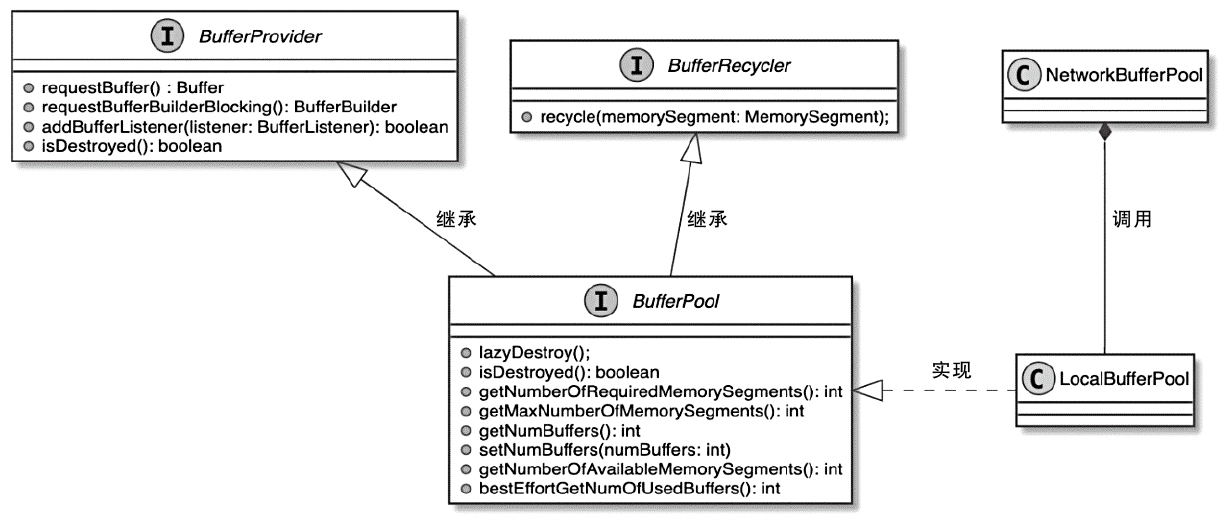
LocalBufferPool 相关类图
FloatingBuffer和ExclusiveBuffer
Exclusive Buffers
- Purpose:
- Pre-allocated buffers exclusively assigned to individual InputChannels (ICs).
- Ensure guaranteed buffer availability for each channel, preventing starvation.
- Key Features:
- Fixed allocation (e.g., 2 buffers per channel).
- Marked in dark color in your image.
- Example: ICs in InputGate-1/InputGate-2 have dedicated buffers for steady data flow.
Floating Buffers - Purpose:
- Dynamically shared buffers across all InputChannels within a LocalBufferPool.
- Handle temporary spikes in data volume or uneven workloads.
- Key Features:
- Flexible allocation (e.g., 8 floating buffers per InputGate).
- Marked in light color in your image.
- Example: Bursty data arriving at an IC can borrow floating buffers from the LocalBufferPool.
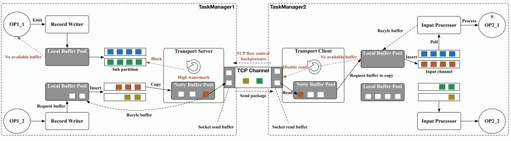
Transfer of a byte buffer between two tasks
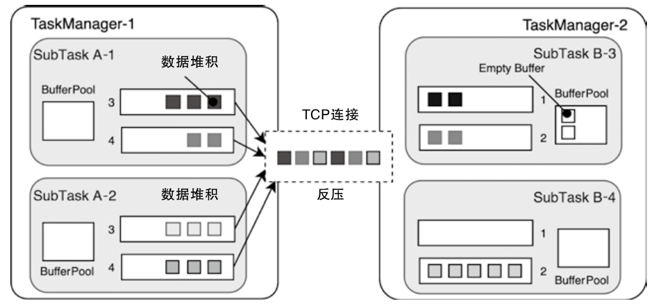
反压机制
TCP自带反压机制
- tcp连接被多个task复用,一个下游的 task 阻塞,会影响上游的 tcp 滑动窗口
- 进而影响上游的 task-manager 中的所有 task
- 上游 ResultPartition 只能根据 tcp来被动感知,不能提前调整发送频率
- 也不能根据 ResultPartition 当前数据挤压情况及时调整下游节点的数据处理速度
1、Core Principles
- Credit Allocation:
- Downstream tasks allocate credits (numerical values) to upstream tasks, indicating the maximum amount of data (measured in buffers) they can currently process.
- Example: If a downstream task has 10 available buffers, it sends a credit of 10 to the upstream task.
- Data Transfer Regulation:
- The upstream task sends data in chunks (buffers) and deducts credits accordingly. Once credits are exhausted, it pauses sending until new credits are received.
- This ensures the upstream never overwhelms the downstream with unprocessable data.
- Dynamic Feedback Loop:
- As the downstream processes data and frees buffers, it periodically sends updated credit values to the upstream, enabling resumption of data flow
2、Key Components
- Buffer Management:
- Buffers (default size: 32 KB) are the units of data transmission. Each buffer corresponds to one credit.
- Downstream tasks manage a LocalBufferPool to track available buffers, which directly determines credit values.
- Credit Messaging:
- Credits are communicated via control messages (e.g., AddCredit messages in Flink’s Netty layer).
- This decouples flow control from the data plane, reducing latency.
- Backlog Awareness:
- Upstream tasks include backlog size (queued but unsent buffers) in data transmissions, allowing downstream to prioritize resource allocation
Workflow Steps
- Initialization:
- The downstream task allocates initial credits (e.g., 10) to the upstream task.
- Data Transmission:
- The upstream sends buffers, decrementing credits for each buffer sent.
- Example: Sending 5 buffers reduces credits from 10 to 5.
- Credit Depletion:
- When credits reach zero, the upstream pauses transmission, preventing data buildup in the network layer.
- Feedback and Renewal:
- After processing data, the downstream frees buffers and sends new credits (e.g., 8) to the upstream.
- The upstream resumes sending based on the updated credits.
基于信用值的反压机制设计
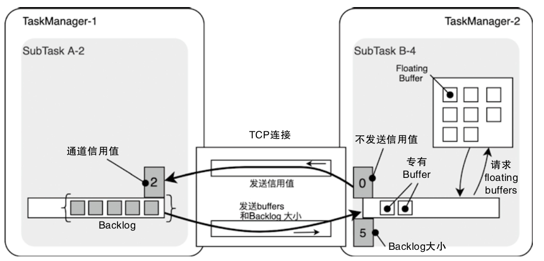
Backlog和Credit的更新逻辑
- Backlog能够通过指标的变化影响下游RemoteInputChannel中浮动Buffer的数量,提升InputChannel的数据处理能力
- Backlog越大说明上游堆积的数据越多,需要更多的Buffer空间存储上游的数据
- 将Credit理解为下游处理数据能力的体现
- RemoteInputChannel中AvailableBuffer的数量发生变化时,会将该信息转换为信用值发送给ResultPartition,表明下游具备数据处理能力,可以处理更多的Buffer数据,即通过信用值控制上游Task发送数据的频率
- ResultPartition通过Backlog控制下游处理数据的能力
- RemoteInputChannel通过信用值控制上游发送数据的频率
每个 creadit 表示一个上游的 buffer(默认 32KB)
一些优化的案例
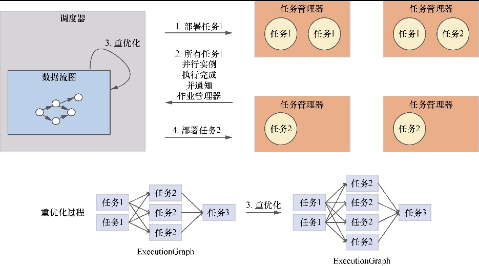
重优化过程
- 类似于 spark 的 AQE,动态收集运行时信息
- 然后运行时调整执行计划
- 可以做分区拆分,分区合并
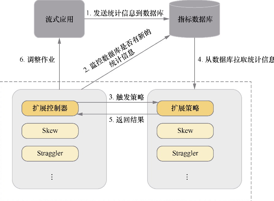
DS2模型架构
- 也是动态收集信息
- 然后动态调整并行度
- 基于论文:Three steps is all you need: fast, accurate, automatic scaling decisions for distributed streaming dataflows
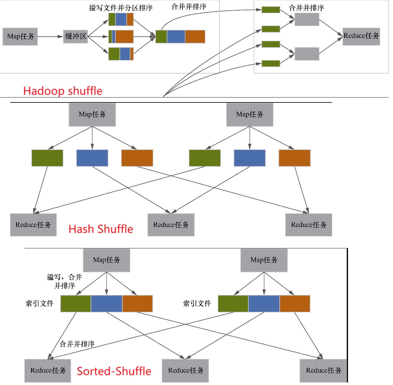
基于 sort 的 shuffle
- 类似于 spark 的 sort-shuffle
- 排序之后有一个索引文件,单个最终排序后的文件
- 索引基于key 的 offset 指向排序的文件
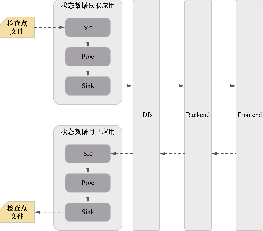
将状态数据进行可视化和修改的架构
- 根据状态信息设计表结构
- 将状态信息写入到数据库,前端再异步处理展示
参考
- 1.20 官方文档
- Lansonli技术博客
- 深入浅出理解Flink运行时架构
- Flink Execution Graph
- Flink实战(11)-Exactly-Once语义之两阶段提交
- Flink on k8s 讲解与实战操作
- Flink Checkpoint 原理流程以及常见失败原因分析
- Stateful Stream Processing
- A Deep-Dive into Flink’s Network Stack
- Analysis of Network Flow Control and Back Pressure: Flink Advanced Tutorials
- 批流统一计算引擎的动力源泉—Flink Shuffle机制的重构与优化
- 业界RemoteShuffleService实现汇总
- Flink Pluggable ShuffleService源码阅读
- Flink Remote Shuffle 开源:面向流批一体与云原生的 Shuffle 服务
- 详细图解 Netty Reactor 启动全流程 | 万字长文 | 多图预警
- Netty Reactor 工作架构图
- Flink架构,源码及debug